


1、Classification of VOCs organic waste gas
VOCs refer to organic compounds with a saturated vapor pressure greater than 133.32 Pa at normal temperature and a boiling point below 50-260°C at normal pressure, or any volatile organic solid or liquid at normal temperature and pressure.
According to the chemical structure, VOCs can be divided into eight categories: alkanes, aromatics, alkenes, halocarbons, esters, aldehydes, ketones and others. Its main components are hydrocarbons, halogenated hydrocarbons, oxygen hydrocarbons and nitrogen hydrocarbons, including benzene series, organic chlorides, freon series, organic ketones, amines, alcohols, ethers, esters, acids and petroleum hydrocarbon compounds. Specifically, there are aromatic hydrocarbons (benzene, toluene, xylene, styrene, etc.), aliphatic hydrocarbons (butane, n-butane, gasoline, etc.), halogenated hydrocarbons (carbon tetrachloride, chloroform, vinyl chloride, etc.) , Freon, etc.), alcohols, aldehydes, ketones, polyols (methanol, propanol, isobutanol, formaldehyde, acetaldehyde, acetone, cyclohexanone, etc.), ethers, phenols, epoxy compounds (ether, methyl phenol, phenol, ethylene oxide, propylene oxide, etc.), esters, acid compounds (ethyl acetate, butyl acetate, etc.), amines, nitrile compounds (dimethylformamide, acrylonitrile, etc.) and others ( Methyl bromide, chlorofluorocarbons, etc.) and other 8 categories
2、Sources of VOCs organic waste gas
1. Sources of VOCs gas in coal chemical enterprises
The waste gas produced in the process of coal chemical industry mainly comes from the two processes of coal-to-coke and coal-to-gas.
1.1 Coal coke waste gas.
It mainly comes from the process of coal charging, coking, and chemical production recovery. In the stage of coal loading, coal raw materials are in direct contact with the atmosphere at high temperature, which will produce a large amount of smoke and dust, and a variety of organic polycyclic aromatic hydrocarbon gases that are harmful to human body; coal coking vocs waste gas mainly comes from chemical production areas and sewage treatment areas . The chemical production area is divided into cold drum section, desulfurization section, sulfur ammonia section, and crude benzene section. The characteristic pollutants and discharge forms are different in different sections.
1) The fugitive gas in the cold drum section mainly includes ammonia, hydrogen sulfide, naphthalene and a small amount of V0Cs, which come from tar storage tanks, ammonia water tanks, tar intermediate tanks, tar ships, underground water seal tanks and other areas, with continuous exhaust and high concentration Low and high temperature characteristics.
2) The fugitive gas in the desulfurization/ammonium sulfate section mainly contains ammonia, hydrogen sulfide and less VOCs, which come from areas such as mother liquor tank, regeneration tank and foam breaking tank, and has the characteristics of continuous exhaust and high ammonia content.
3) The fugitive gas in the crude benzene section mainly contains benzene series, which comes from areas such as crude benzene storage tank, lean oil tank, oil washing tank, underground tank and crude benzene metering tank, and has the characteristics of small gas volume and high concentration.
4) The waste gas emission in the sewage treatment area is mainly volatile emission and gas entrainment, and the main pollutants are benzene series, hydrogen sulfide and nitrogen, which come from accident pools, regulating pools, anoxic pools, eye gas pools, and sludge filter presses and other areas, which have the characteristics of large gas volume, low concentration and high water content.
1.2 Coal gas waste gas
The coal-to-gas industry mostly adopts fixed-bed pulverized coal pressurized gasification, low-temperature methanol washing acid gas purification, and methane synthesis to generate natural gas. According to the characteristics of the process flow, there are four main discharge points of Vocs: tail gas after washing and purifying acid gas with low-temperature methanol, breathing waste gas from gas and water atmospheric storage tanks, malodorous gas emitted by sewage treatment equipment, and breathing waste gas from storage tanks in tank farms.
1.2.1 The waste gas discharged from low-temperature methanol washing contains methane, ethylene, ethane, propylene, propane, methanol and other substances, which are difficult to recycle. If you want to achieve the purity that can be reused, it is almost unbearable economically, so you can only use destruction The method is to convert VOCs into harmless substances and then discharge them into the atmosphere.
The investment cost of RTO and RCO is roughly the same. Since the combustion temperature of RCO is lower than that of RTO, the operating cost of RCO is lower. However, because the sulfur contained in the exhaust gas will cause the catalyst to be poisoned and deactivated and cannot be regenerated, it is better to choose RTO.
1.2.2 Gas-water storage tank breathing waste gas is mainly unorganized waste gas discharged from the breathing valve of the storage tank, mainly hydrogen sulfide and ammonia, with high VOCs concentration. Due to the influence of ambient temperature, the flow and concentration fluctuate greatly.
This gas has no recovery value, and it can be considered to use RTO for direct combustion. Under the premise that the pressure drop is satisfied, this gas can be transported to the low-temperature methanol washing RTO device for processing through pipelines, saving equipment investment.
1.2.3 Exhaust gas from sewage treatment equipment, the first type of exhaust gas is the gas emitted from the adjustment tank, homogeneous tank, grease trap, acidification hydrolysis tank and other devices of the pretreatment unit, the gas volume and concentration fluctuate in a large range, and the VOCs content is high; The other is the gas in the aeration tank and the sludge dehydration room. The foul smell is obvious. The yield of sulfide and volatile phenol is more than 95%, which greatly reduces the scale of thermal crystallization.
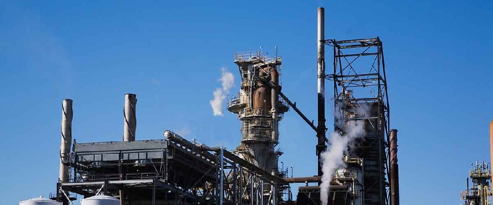
2.Sources of VOCs gas in smelting enterprises
Analysis on the formation mechanism of VOC in the sintering process of iron and steel industry. It is generally believed that VOC: mainly comes from coal combustion. Due to the use of fuel in the sintering process, VOCs are inevitably generated. During the sintering process, VOCs are formed from volatile substances in raw materials such as coke and oily iron oxide scale, and are emitted in the form of gas. Under certain operating conditions, dioxins and furans are simultaneously formed. The temperature range of the sintering preheating zone is basically 100°C-900°C, the thickness is about 100m-200mm, and the duration is about 10 minutes. As the sintering proceeds, the temperature of the fuel particles rises, and the internal organic volatiles volatilize into the airflow in a gaseous state, and move downward with the airflow, the lower temperature is lower, and the temperature of the airflow containing organic volatiles decreases after heat exchange. The boiling point is gradually condensed. Due to the faster condensation, many tiny particles are formed, which is also one of the reasons for the formation of dust.
3.Sources of VOCs gas in packaging and printing enterprises
Packaging and printing classification 1: according to printing materials, paper product packaging printing, plastic packaging printing, metal packaging printing, other packaging printing; classification 2: according to printing methods, lithography (offset printing), gravure printing, flexo printing, embossing printing , silk screen printing, others.
According to relevant data estimates, the total VOCs emissions from the packaging and printing industry exceed 2 million tons. VOCs emissions in the packaging and printing industry are mainly concentrated in the production processes of printing, drying, compounding and cleaning, mainly from inks, adhesives, coating solutions, fountain solutions, car wash water, various solvents, etc. Natural volatilization and drying volatilization of materials.
The plastic color printing and flexible packaging industry is the main force of VOCs emissions in the packaging and printing industry. In order to achieve the product effect, organic solvents need to be used in the production process, mainly ethyl acetate, toluene, butanone, isopropanol, etc. Therefore, the plastic color printing flexible packaging industry is the focus of the packaging and printing industry.
4.Sources of VOCs gas in surface coating enterprises
Surface coating generally refers to the production process of paint blending, coating (including primer, primer, topcoat, varnish), leveling, drying and other links in industrial production. According to the classification in the "National Economic Industry Classification" (GB/T4754-2017), the surface coating classification involving VOCs treatment generally includes furniture manufacturing (C21), metal products industry (C33), general equipment manufacturing (C34) , special equipment manufacturing industry (C35), automobile manufacturing industry (C36), railway, ship, aerospace and other transportation equipment manufacturing industry (C37), metal products, machinery and equipment repair industry (C43) VOCs in the coating production process of enterprises pollution prevention and control management.
3、RTO regenerative incineration process
1.RTO regenerative incineration process route
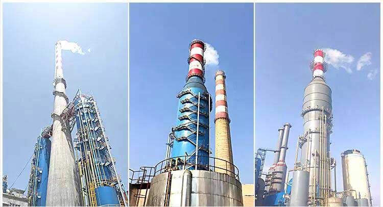
1.1 How RTOs work
Take the three-bed RTO as an example. After the RTO is preheated, the exhaust gas enters the first ceramic heat storage area through the switching valve for preheating, and stays in the high-temperature combustion area for at least one second. The burner ignites natural gas to make the temperature in the chamber When it is raised to 850°C, the exhaust gas is fully oxidized. The purified gas flows through the second ceramic heat storage area, so that up to 97% of the combustion heat is recovered, waiting for the next cycle, and used for preheating the normal temperature exhaust gas. After about 1-2 minutes, the switching valve changes the direction of the gas in and out, the exhaust gas enters from the second heat storage area, and is discharged from the third heat storage area, and the first heat storage area becomes a purge state, returning the exhaust gas that is not fully burned Go to the entrance of RTO-G and start again and again.
1.2 RTO process characteristics
①.Excellent safety control solution, fast poppet valve switching system, leakage less than 1%, automatic combustion sequence control, flame monitoring, system self-test, fault detection.
②.PLC automatic control, simple operation, stable operation and high reliability
③.Stacked or tiled design, suitable for occasions with load or height restrictions (such as building roofs)
④.The processing efficiency is high, up to 99.95%, and the heat exchange efficiency of the ceramic regenerator is as high as 97%, effectively reducing gas consumption
1.3 RTO performance parameters
①.Processing capacity: 5000~500000Nm3/h
②.Design operating temperature: 760~850°C
③.Heat Exchange Medium: Ceramic
④.Process pressure drop: 900~1200 Pa
⑤.Main body insulation material: ceramic fiber module
⑥.Auxiliary energy: natural gas or diesel
⑦.Switching system leakage: <0.05%
⑧.Processing capacity: up to 99.95%


4、RCO regenerative catalytic combustion process
RCO regenerative catalytic combustion
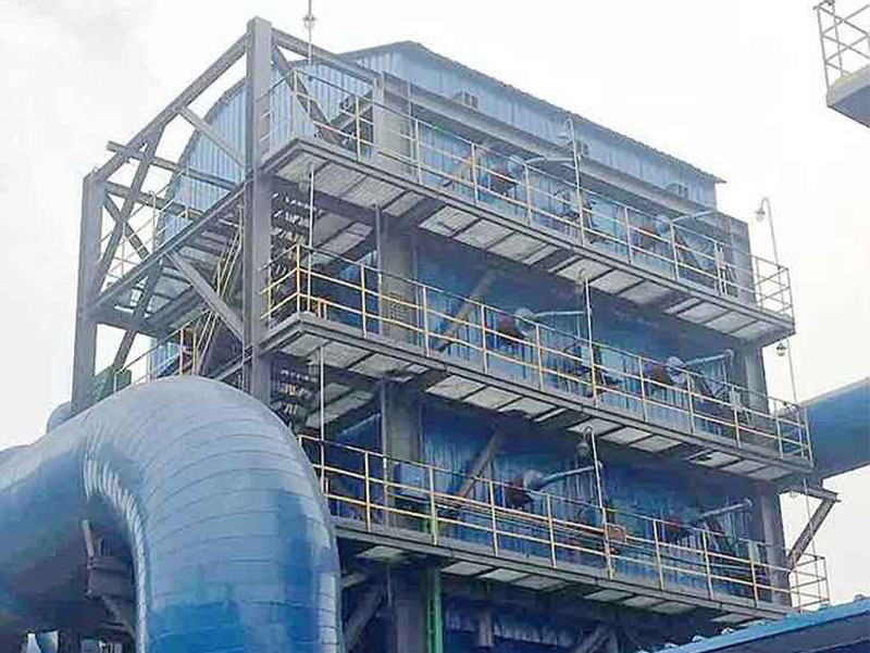
Regenerative catalytic oxidation furnace (RCO) is based on the structure of RTO, and a layer of precious metal catalyst is added to the oxidation furnace to reduce the activation energy of chemical reactions and change the reaction conditions to achieve lower temperature oxidation to remove organic waste gas Purpose. The device of RC0 is similar to the device of RTO, which adopts bed type or rotary design, and the ceramic regenerator in the regenerator chamber is used to replace the heat released from the reaction. First, it enters the regenerator through the flame arrester of the front-end dust collector, and performs heat exchange in the regenerator, at about 200-400°C, and then oxidizes under the action of a catalyst through the oxidation chamber. If the reaction temperature cannot be reached, the heating system can be realized through the automatic control system. Compensation heating, the high-temperature flue gas that has been oxidized enters another heat exchange chamber to exchange heat, and the low-temperature purified flue gas is discharged into the atmosphere through the chimney.
The host of catalytic oxidation equipment is composed of flame arrester, heat exchanger, preheater, catalytic reaction chamber, main exhaust fan, control system, electric heating component and catalyst, which is the core component of the equipment.
1.Process characteristics
Catalytic combustion equipment can effectively reduce heat loss and energy consumption resources, while greatly reducing the emission of purified gas
①Easy to operate, small footprint
②Low energy consumption: when a certain concentration is reached, no power (or low power) operation
③Safe and reliable: pressure relief, self-protection, fire prevention and dust removal, over-temperature alarm and advanced automatic control
④Small resistance and high efficiency: advanced metal-impregnated honeycomb ceramic catalyst with large specific surface area.
⑤Long service life: the catalyst is generally replaced within one year, and the carrier can be regenerated